Laser on Evo

Step #06 - Modifying the Control Unit

List of Components

ItemSpecQty
 GX12 Male Connector5-pins1
 Wago Connector3-way3

Tools needed

Allen key 2mm Spanner 12mm Spanner 15mm Flat head screwdriver
This step is only necessary if you have purchased and assembled your machine before ordering the laser. If you bought both at the same time, you can skip this step, as the connector will already be wired inside the control unit.
Don't worry about removing the Warranty Void sticker, we keep every customer's purchase history and your machine will still be under warranty if you don't modify anything else inside the control unit.
Instructions

  1. Unscrew the M3x4 screws on the side of the control unit and remove the cover.
    1. Remove the M12 counter-nut and washer from the GX12 connector.
      1. Remove the plastic cap and place the connector in the bottom right hole provided on the control unit, then tighten it with the same nut and washer, using both spanners.
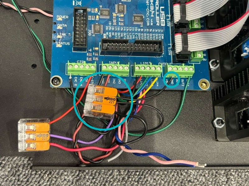
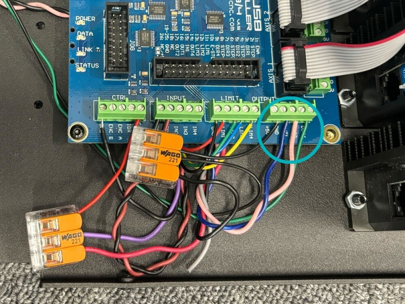
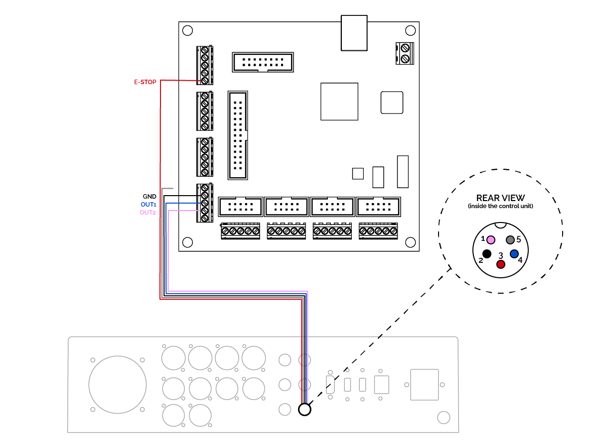
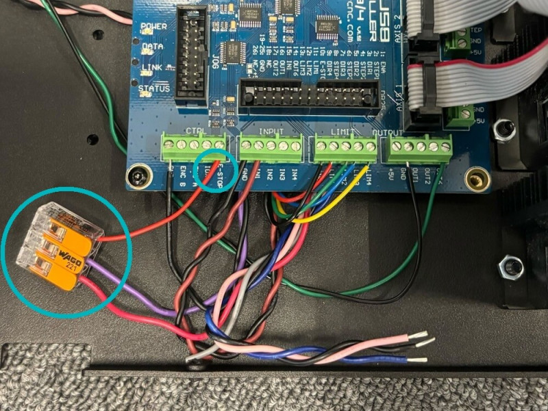
        1. Wire the connector to the controller, as shown in the connection diagram below. As some terminals already have a wire in them, use the Wago connectors provided to connect both to the same terminal.
          1. Cut the end of the grey wire, as it is not used.
            1. Reinstall the cover and close it with the screws.

              Animation

              Connection Diagram

              This connection diagram applies to a control unit with AMB DI spindle.