Assembly Guide
| Pictures | |
| 5 hours | |
| Allen key 3/4/5mm, Spanner 8/10mm |
#1 Z-axis Disassembly
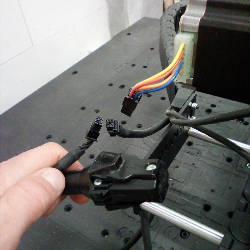
1. Unplug all the motor cables, including the spindle.
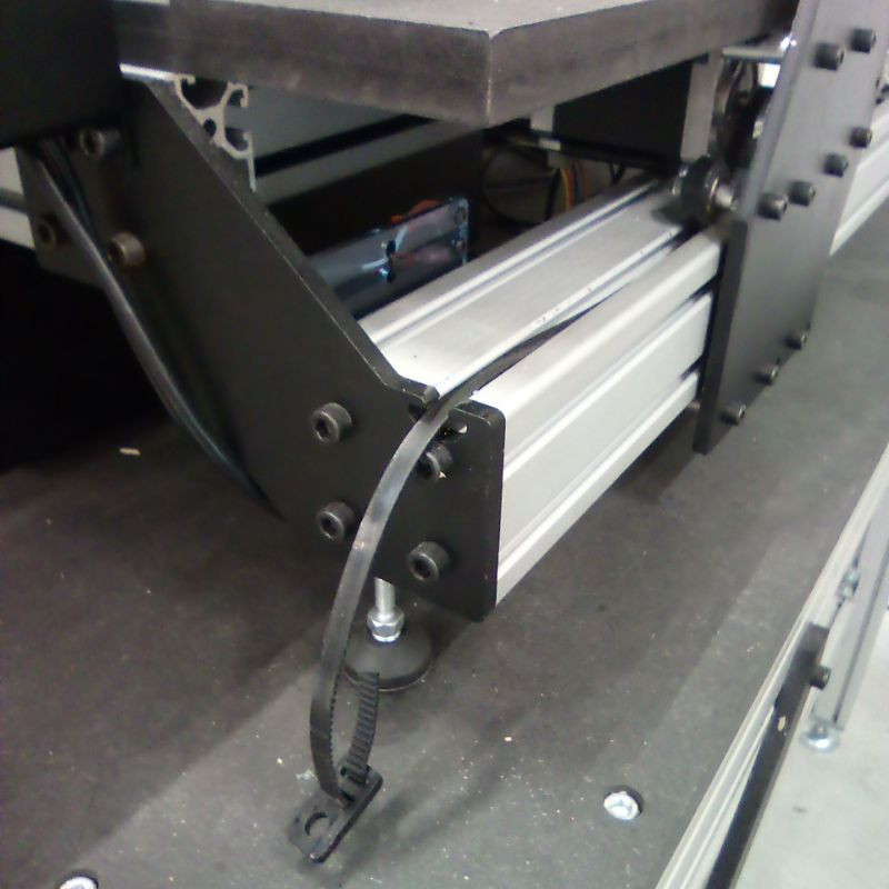
2. Cut the cable ties to detach the cables from the gantry.
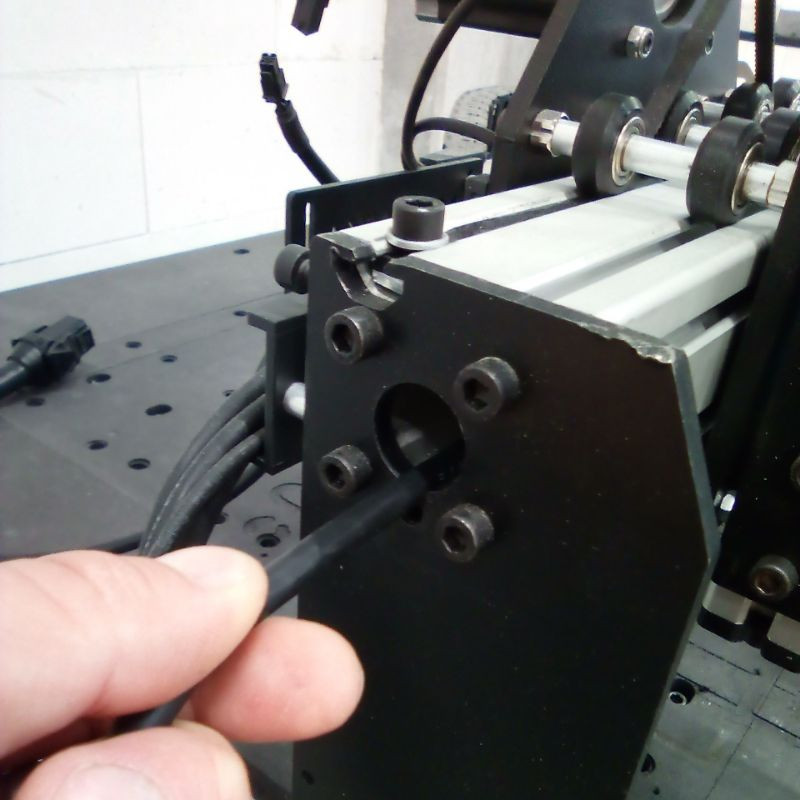
3. Pull the Y2 motor cable out of the X-axis 6060 profile.
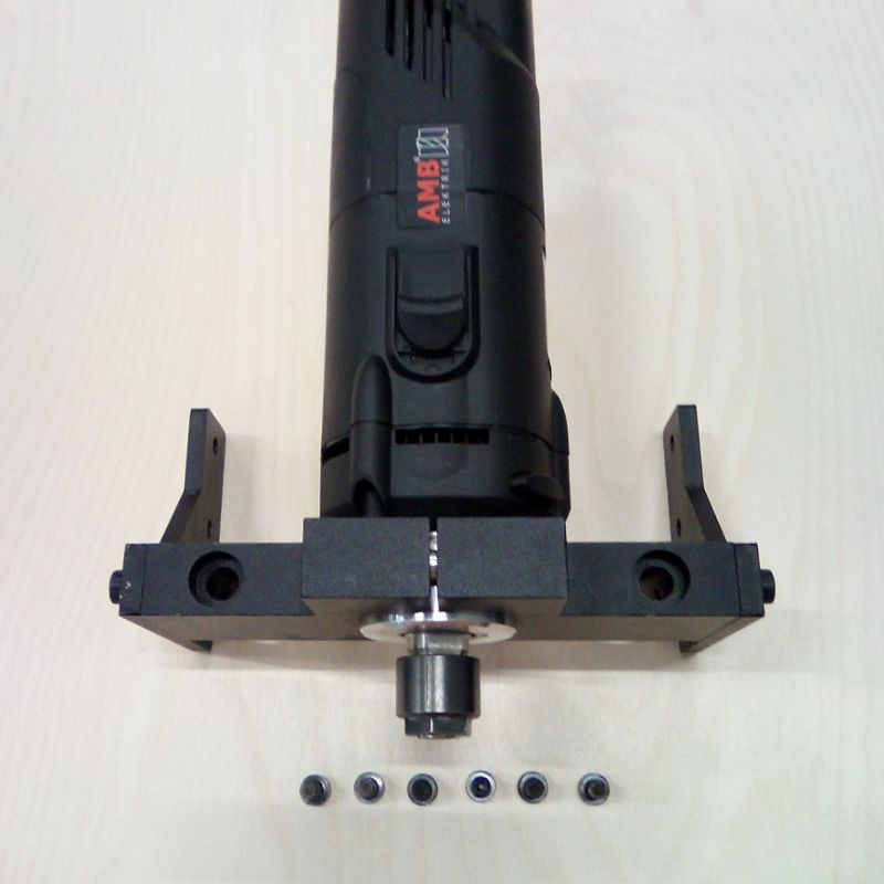
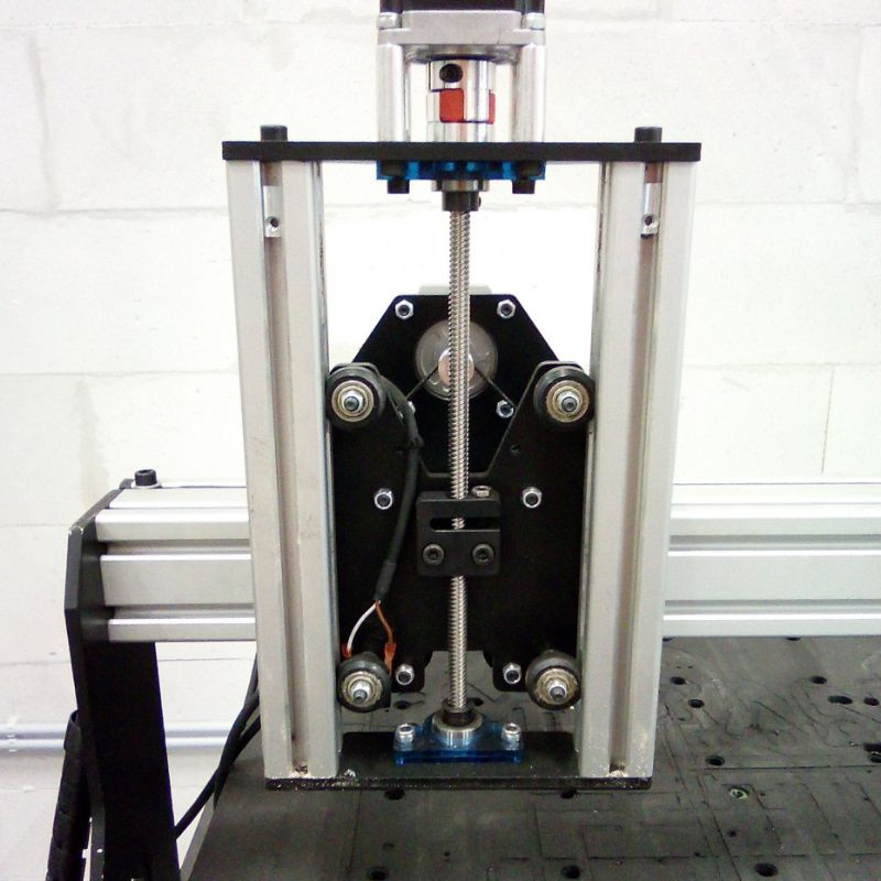
4. Remove the spindle from the Z-axis block.
5. Remove the blue protection sheet.
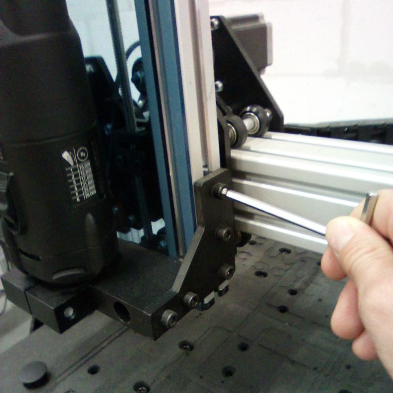
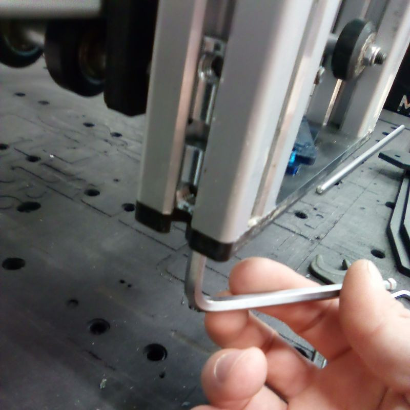
6. Unscrew the two screws to remove the bottom steel plate.
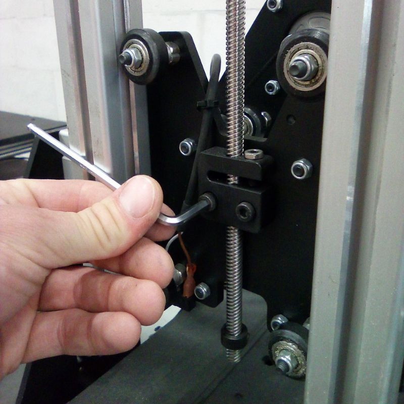
7. Unscrew the anti-backlash nut.
8. Remove tension from the wheels using the eccentric spacers, then slide the whole Z-axis block up and remove it from the machine.
9. Untighten the two stop rings.
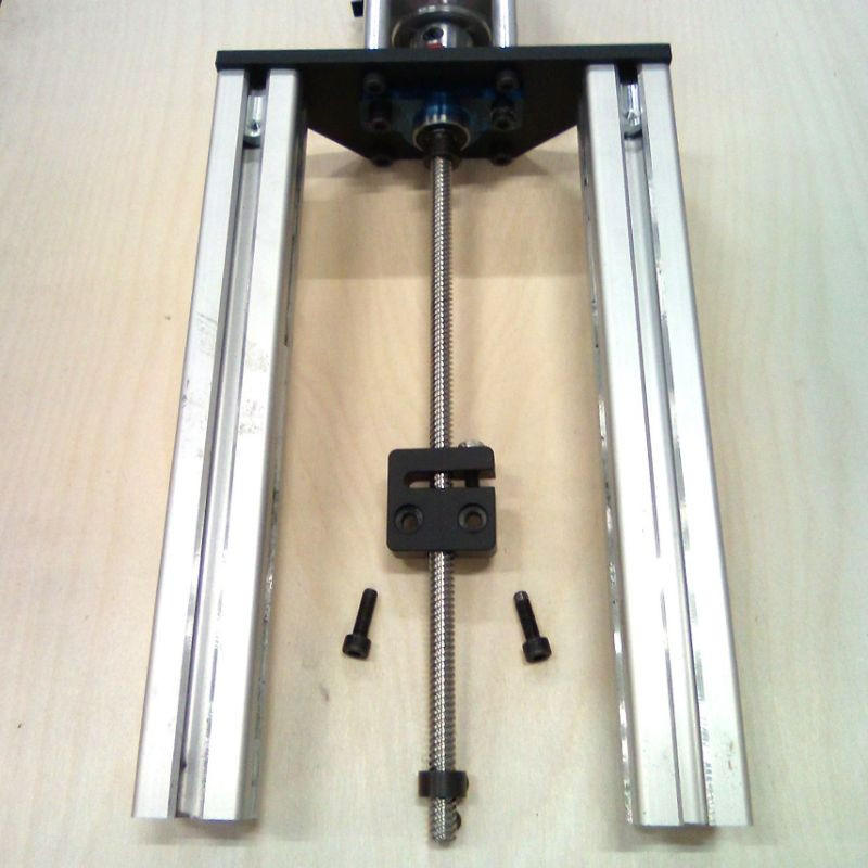
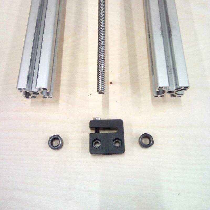
10. Remove the anti-backlash nut and the two stop rings from the lead screw.
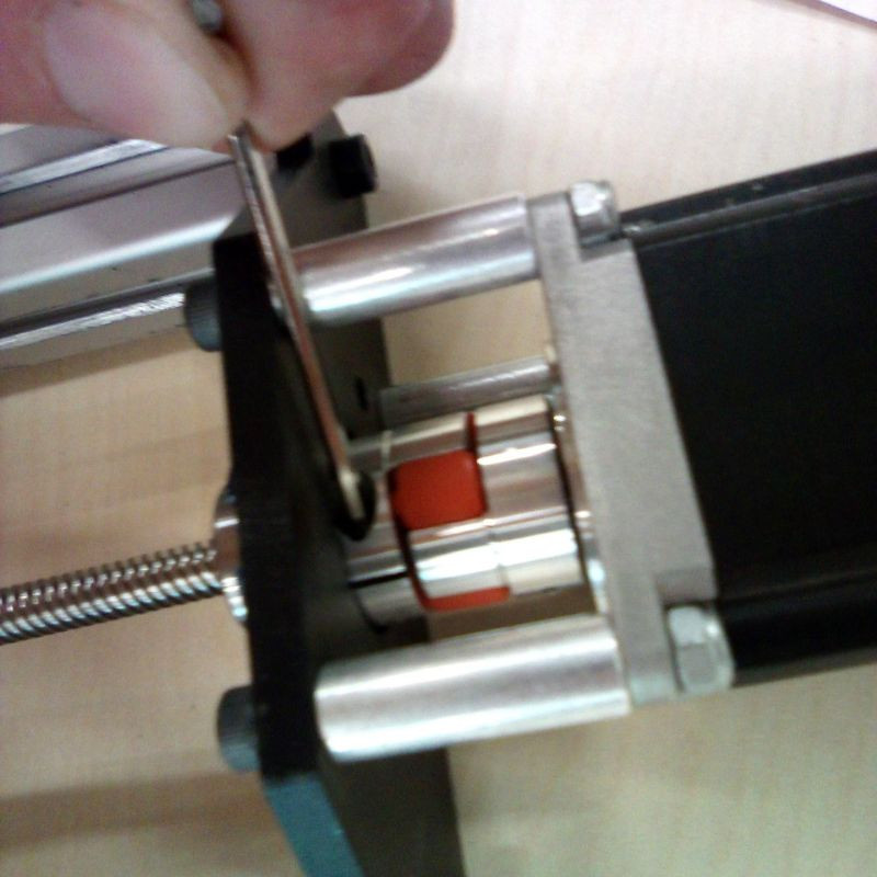
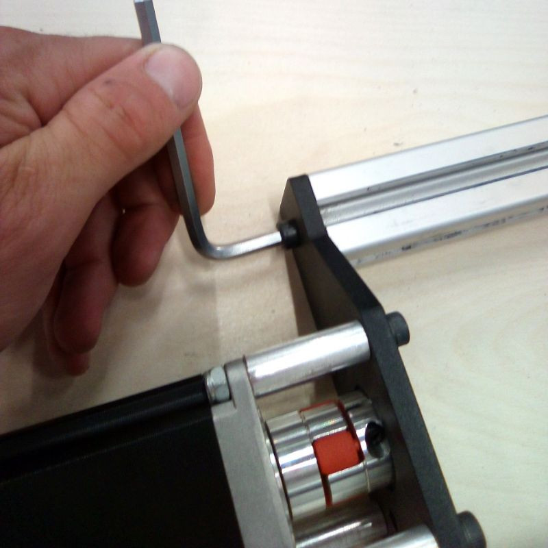
11. Untighten the motor coupler, on the lead screw's side only.
12. Remove the lead screw.
13. Remove the two 3030 profiles.
14. Put the motor and steel plate assembly aside.
#2 Y-axis Gantry Disassembly
15. Unscrew the 6060 profile from the two gantry plates. Be careful when removing the last screw, it is heavy! Ideally, ask for help, or put support under the profile.
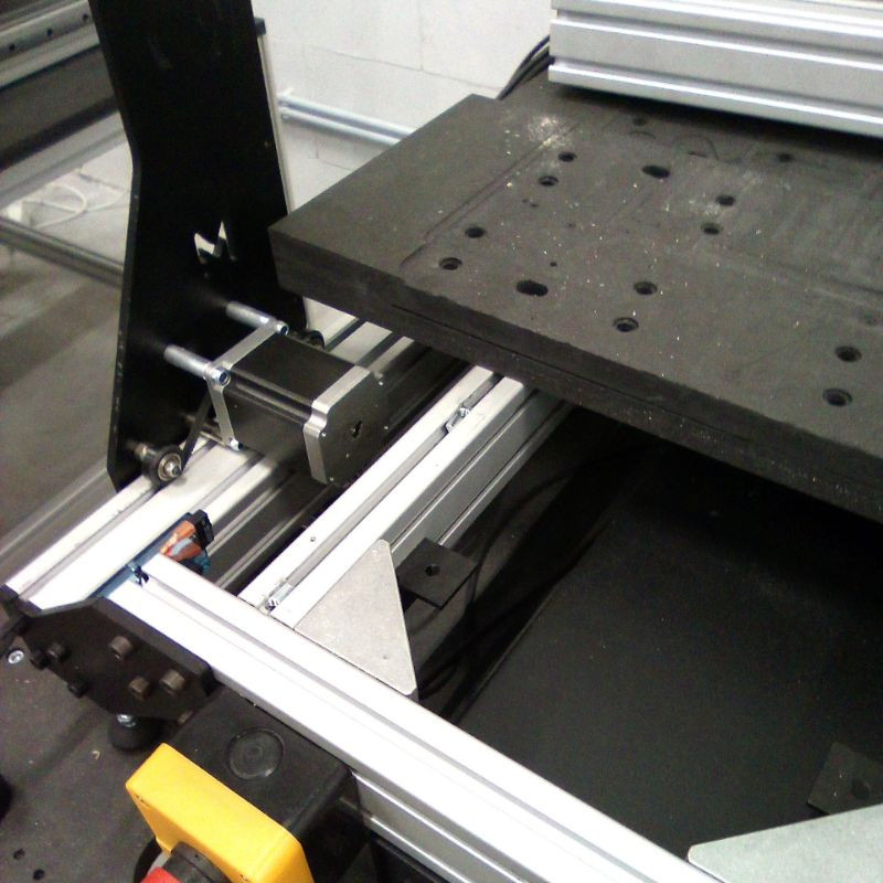
16. Carefully lay the X-axis assembly on the table frame.
17. Remove the front part of your spoilerboard.
18. Detach the cable chain from the gantry on the Y1 side (left).
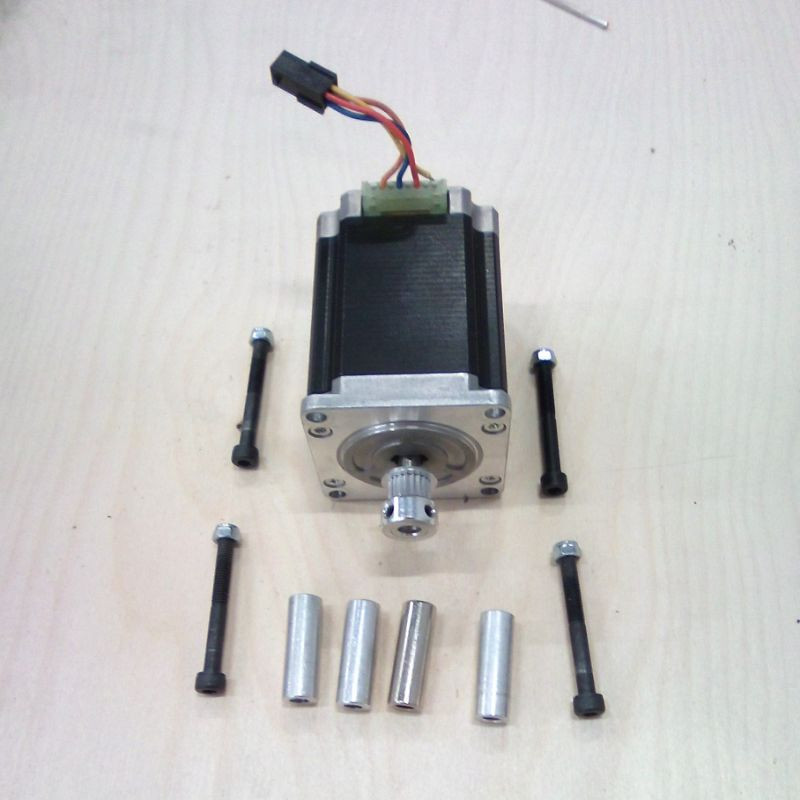
19. Remove the motors on both the Y1 and Y2 axes.
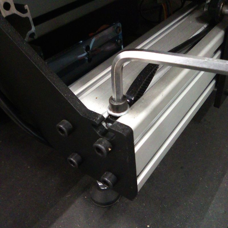
20. Detach the belts at the front of the Y1 and Y2 axes.
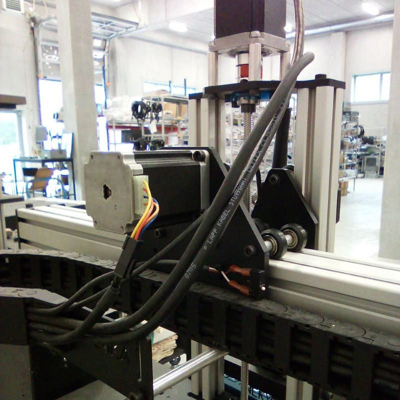
21. Remove the tensioning system from the profile's slot.
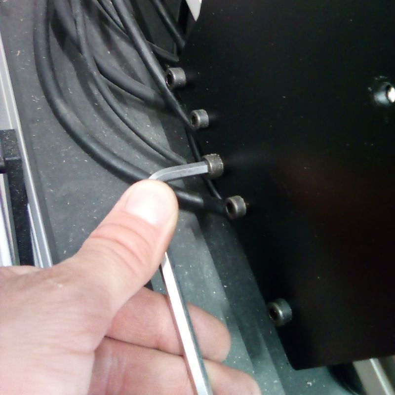
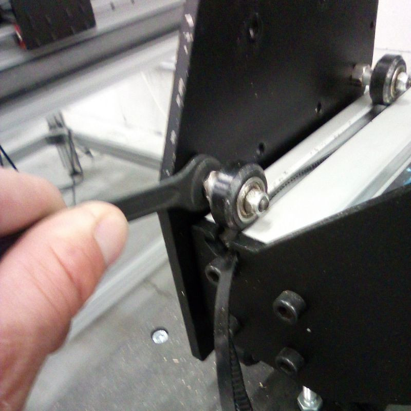
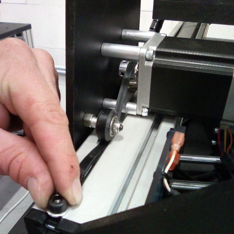
22. Untighten the wheels on both gantry plates, using the eccentric spacers.
23. Remove both gantry plates by sliding them outside of the profiles.
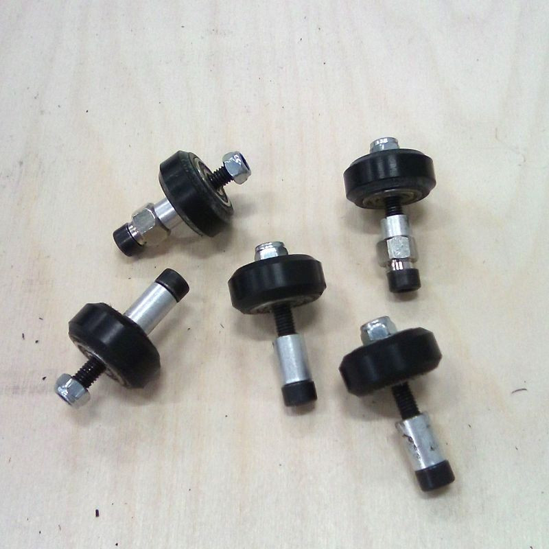
24. Remove all the wheels from the gantry plates.
#3 High-Z Gantry Assembly
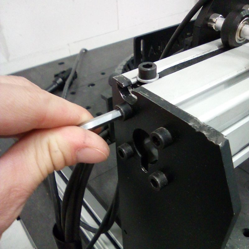
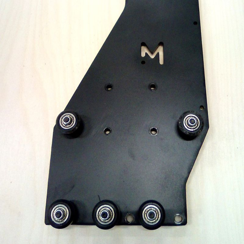
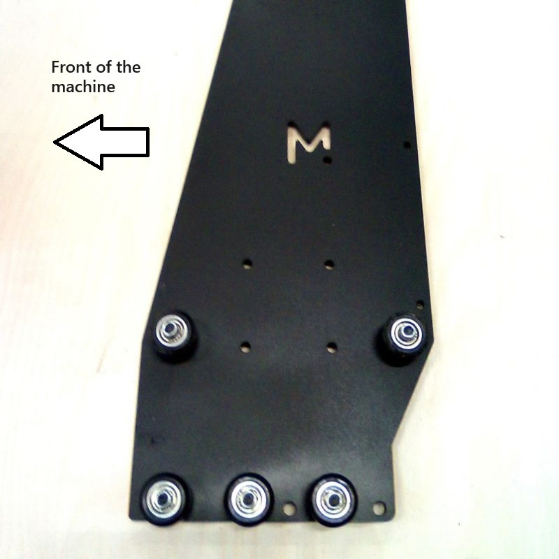
25. Re-assemble them on the new high gantry plates, exactly as it was. Do not fully tighten the wheels yet. Pay attention to the orientation of the gantry plates when assembling the wheels.
26. Slide the new gantry plates into the Y1 and Y2 profiles (the picture above shows the left gantry part that will go on the Y1 profile).
27. Fully tighten all the wheels, making sure that they are straight and lay in the middle of the profile's slot.
28. Use the eccentric spacers to tighten the gantry plates onto the profile. The wheels should all be in contact with the profile and slide smoothly.
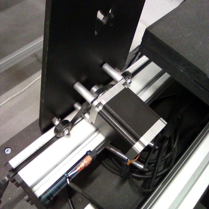
29. Re-assemble the motors with the connector facing down. Make sure that the belt goes above the pulley.
30. Firmly re-tighten the belts on both sides.
31. Carefully attach the X-axis 6060 profile to the gantry plates. Again, you might require some help for this step.
32. Firmly re-tighten the the belts on the X-axis.
#4 High-Z Block Assembly
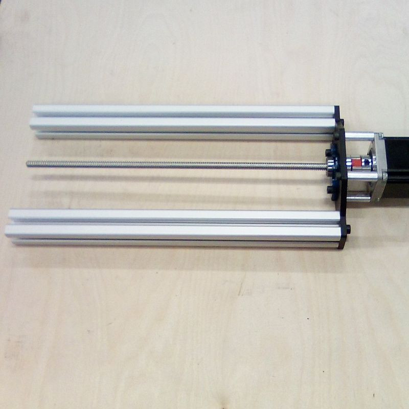
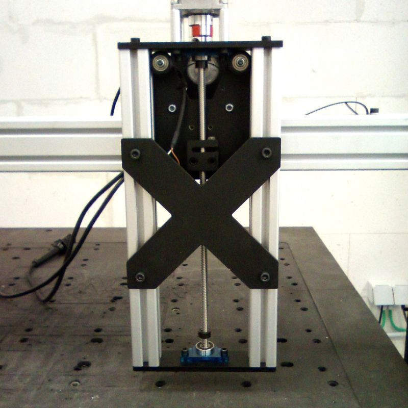
33. Attach the two 340mm 3030 profiles to the Z-axis top plate.
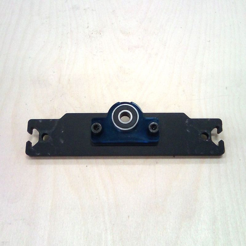
34. Insert the 350mm lead screw inside the bearing, all the way to the motor coupler.
35. Firmly tighten the motor coupler.
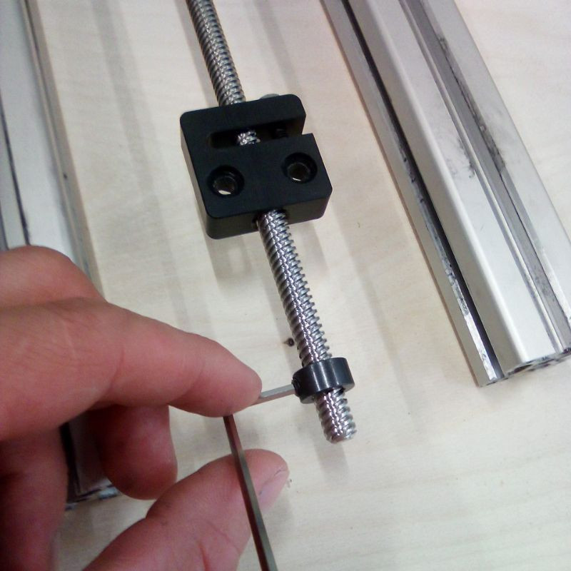
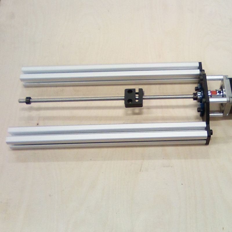
36. Insert the first stop ring on the lead screw, and tighten it all the way up against the bearing.
37. Insert the anti-backlash nut.
38. Insert the second stop ring on the lead screw, and tighten it slightly so it doesn't fall.
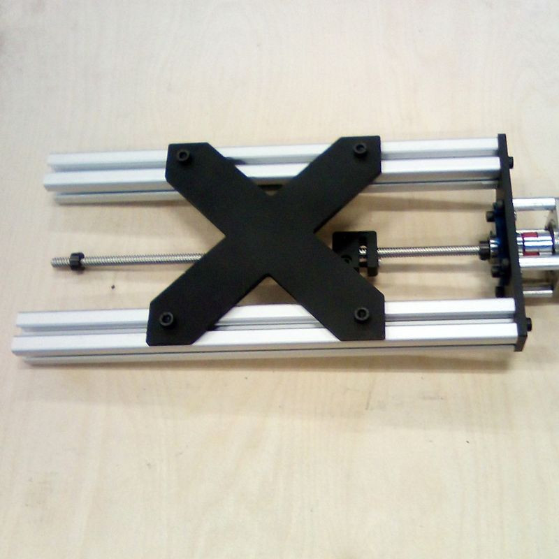
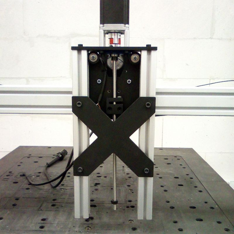
39. Attach the X cross plate to the profiles, a bit lower than the middle (it will ease access to the eccentric spacers later).
40. Slide the Z-axis black on the wheels of the X-axis carriage.
41. Attach the bottom plate on the Z-axis.
42. Place the stop ring against the lower bearing and tighten it.
43. Use the eccentric spacers to tighten the wheels onto the profiles. They should all be in contact with the profile and slide smoothly.
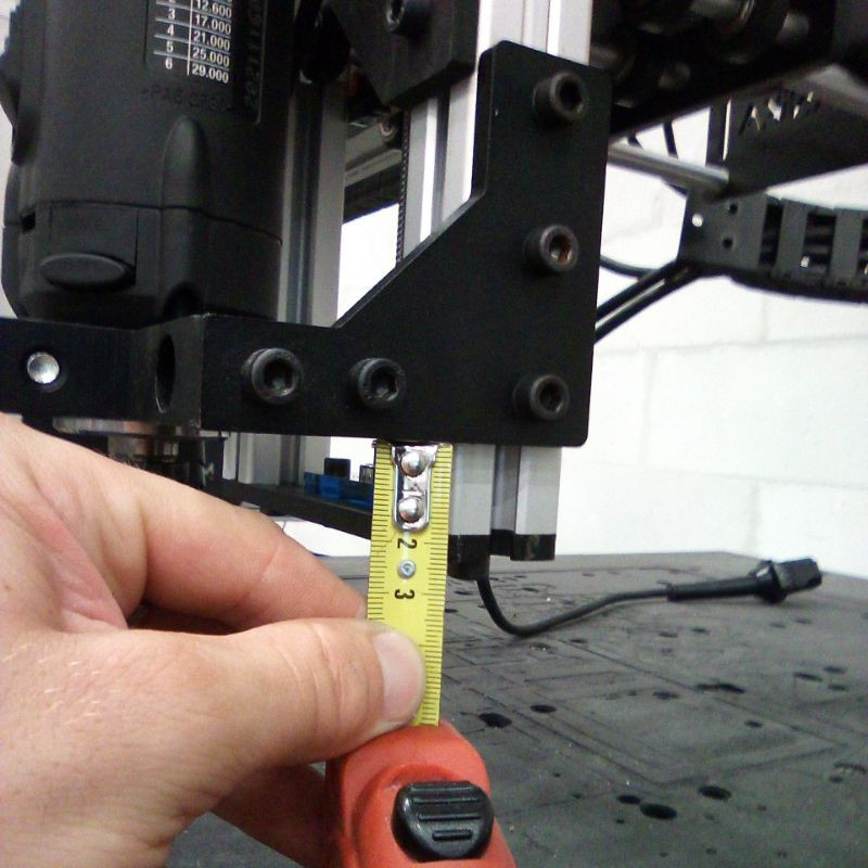
44. Attach the AMB support brackets on both profiles. They should be placed 2cm above the lowest part of the 3030 profiles.
45. Make sure that the spindle is straight and perpendicular in the X and Y directions (we recommend you follow the tramming chapter of the calibration guide one more time to do the spindle tramming).
46. Reconnect all the cables (don't forget the Y1 and Y2 motors).
#4 Configuration & Testing
47. Re-attach the front part of the spoilerboard.
48. Turn on your control unit.
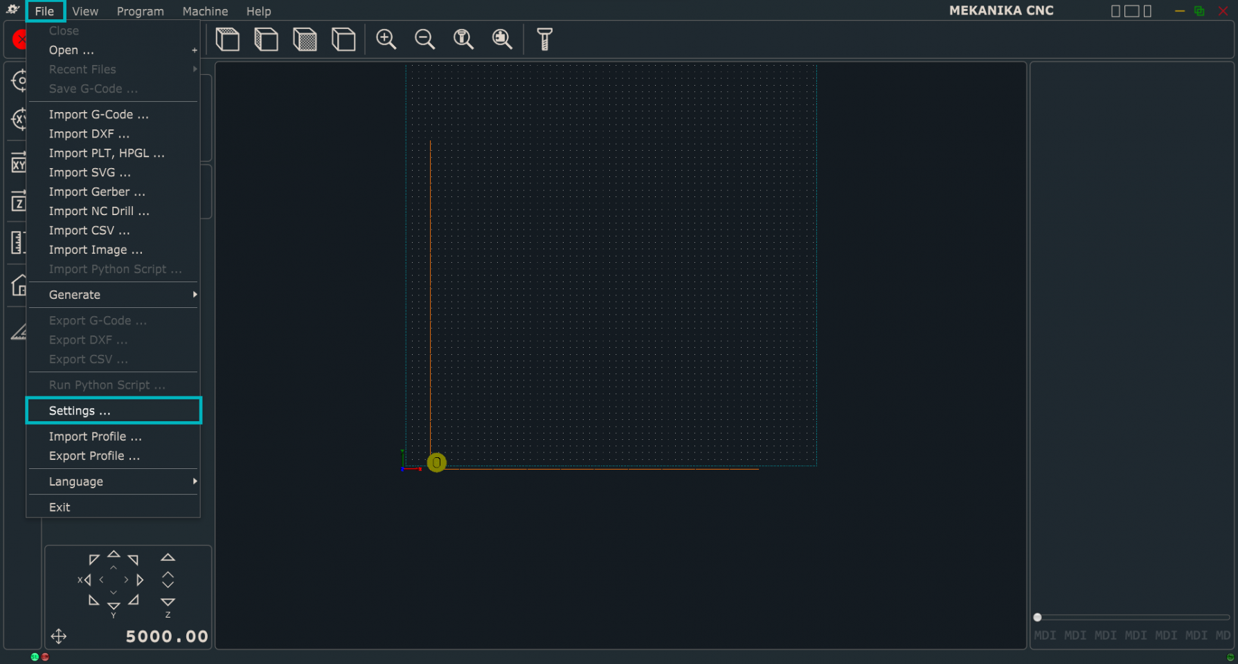
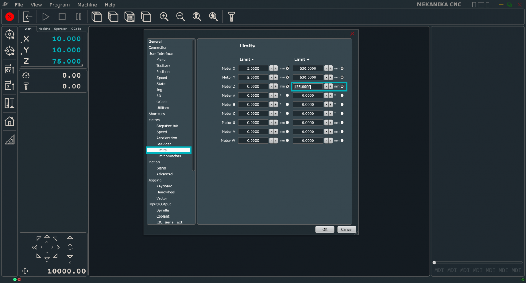
49. Go to the settings of PlanetCNC: File > Settings > Motors > Limits
50. Increase the "Z+ limit" value to 175mm.
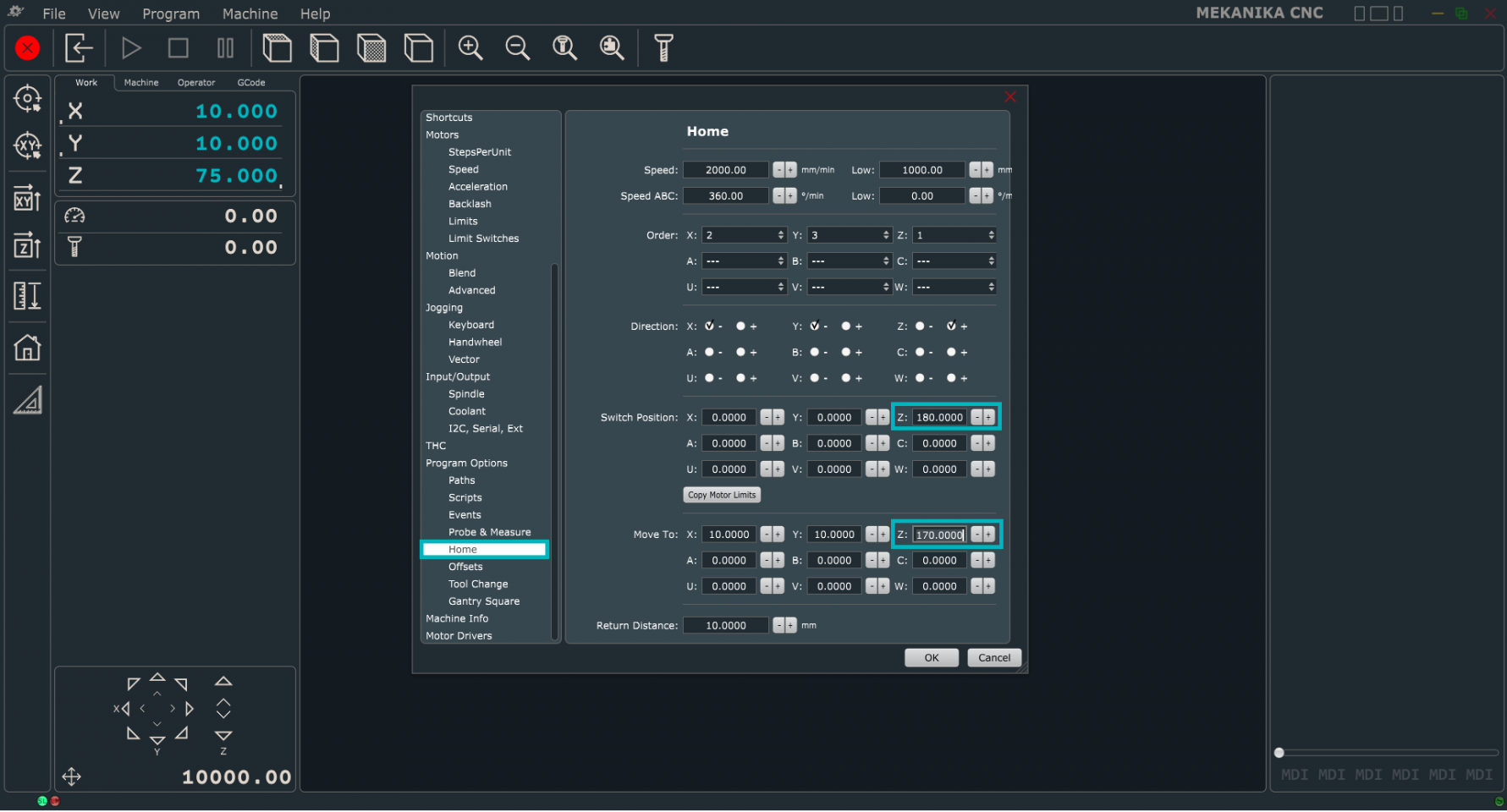
51. Now navigate to Program Options > Home
52. Increase the "Z switch position" value to 180mm.
53 Increase the "Z move to" value to 170mm.
54. Click "OK" to save your settings and try to make a Home procedure. The machine should go all the way up and automatically have the new correct coordinates.
55. Enjoy your new High-Z machine!
