7. Y-axis Motor & Pinion Assembly

Step #04 - Attaching the Pinion Gear

List of Components

ItemSpecQty
 Pinion gear2M2
 ISO7379 shoulder screw12x50/M102
 LocknutM102
 Offset washer 12x16x1mm2
 Offset spacer12x18x8mm2
 Radial bearing12x18x4mm2
 Radial bearing12x37x12mm2

Tools needed

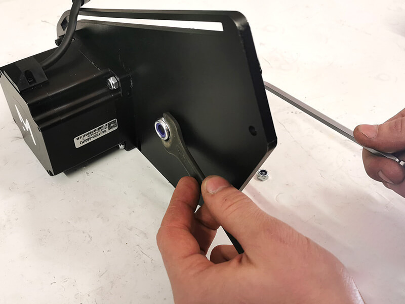
Allen Key 6mm Spanner 17mm

Instructions

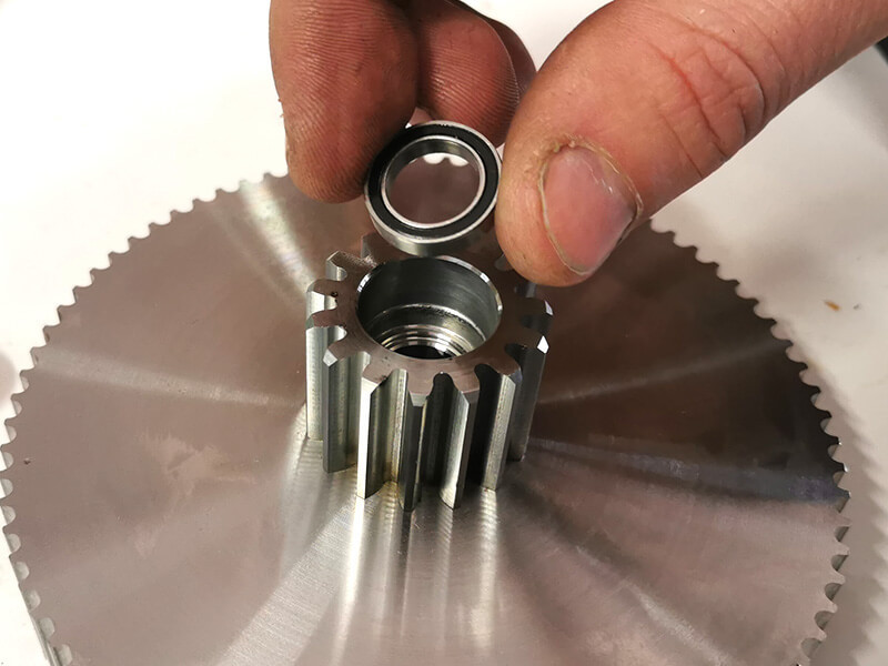
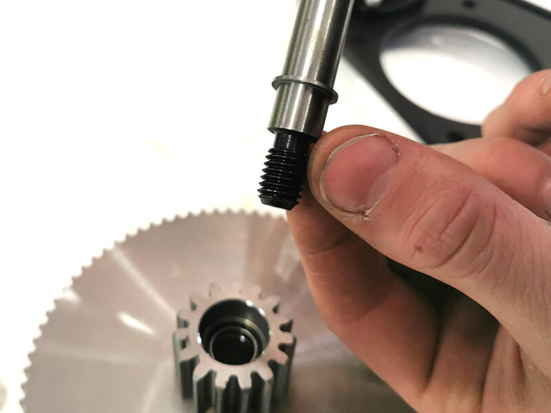
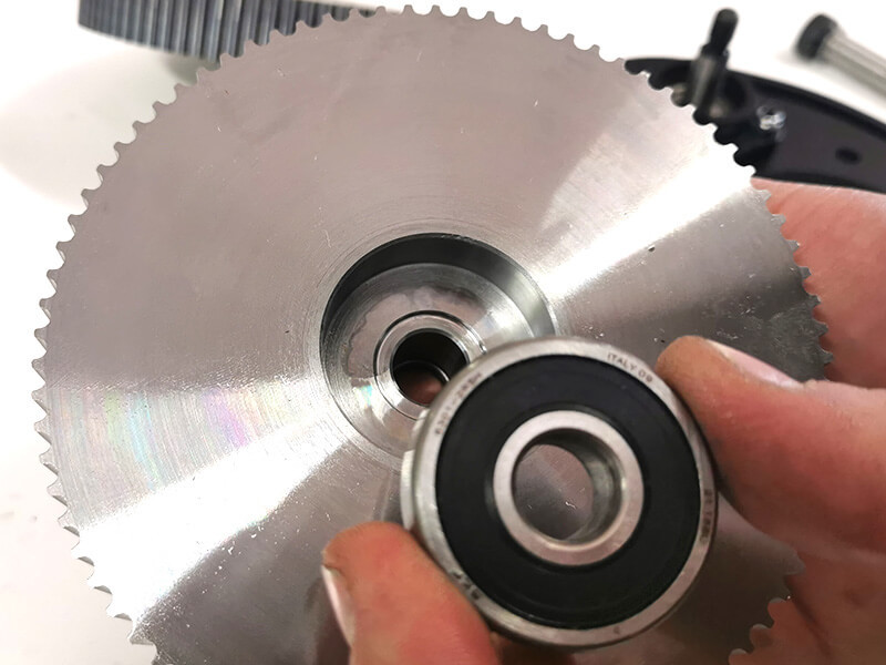
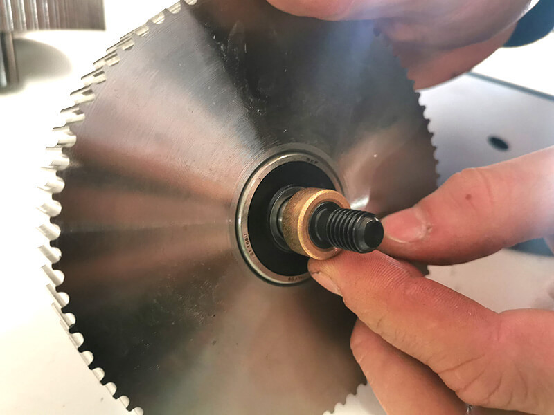
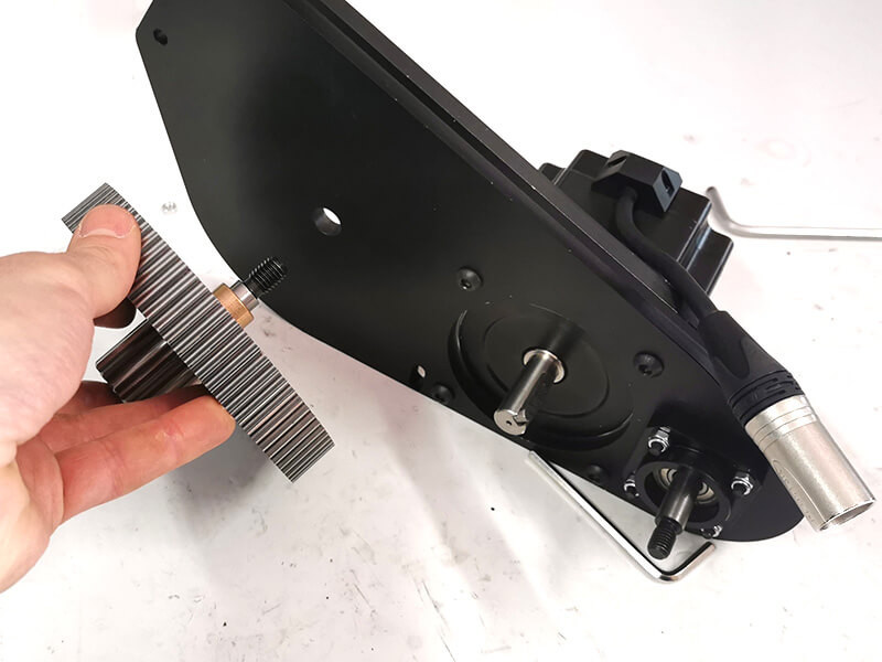
  1. Take the shoulder screw and insert on it the following components in this exact order: offset washer, small bearing, pinion, large bearing and then offset spacer.
    1. Position this assembly on the steel plate, on the opposite side of the motor.
      1. Use the locknut to tighten the assembly (do not overtighten the locknut, see remark below).
        1. Replicate the same assembly on the other side.

          Animation

          Do not over-tighten the locknut, the lockring is there to prevent the disassembly. Too much torque on the locknut will potentially lead to a failure of the small bearing.
          Try to put the pinion in motion, it should turn easily without too much friction. If it is not the case, it means that you over-tightened the screw.