4. Z-axis assembly
Step #05 - Inserting the Leadscrew
List of Components
| Item | | Spec | Qty | High-Z Kit |
|---|
| | Anti backlash Nut | / | 1 | 1 |
| | Threaded rod | M5 | 1 | 1 |
| | Nut | M5 | 1 | 1 |
| | Lead Screw T8 | M8-250mm | 1 | - |
| | Lead Screw T8 | M8-350mm | - | 1 |
| | Stop Ring | / | 1 | 1 |
| |
DIN 912 Screw | M5x16 | 2 | 2 |
| |
DIN 912 Screw | M6x16 | 2 | 2 |
Instructions
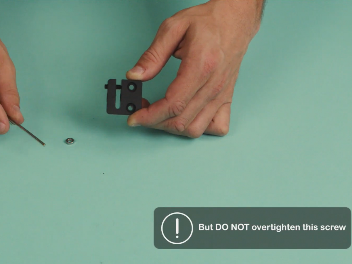
- On the anti-backlash nut, insert the M5 screw until it touches the opposite side. Do not over tighten it !
- Screw down the M5 nut.
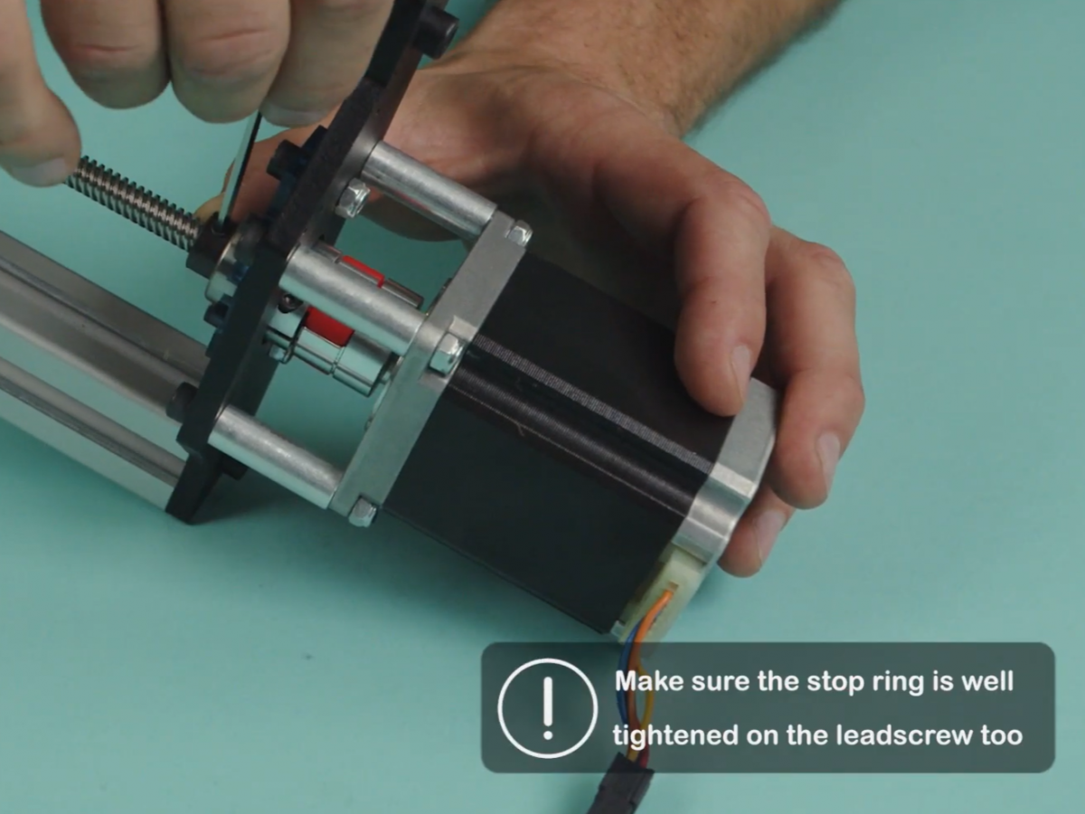
- On the Z-axis assembly, place the stop ring aligned on the bearing support.
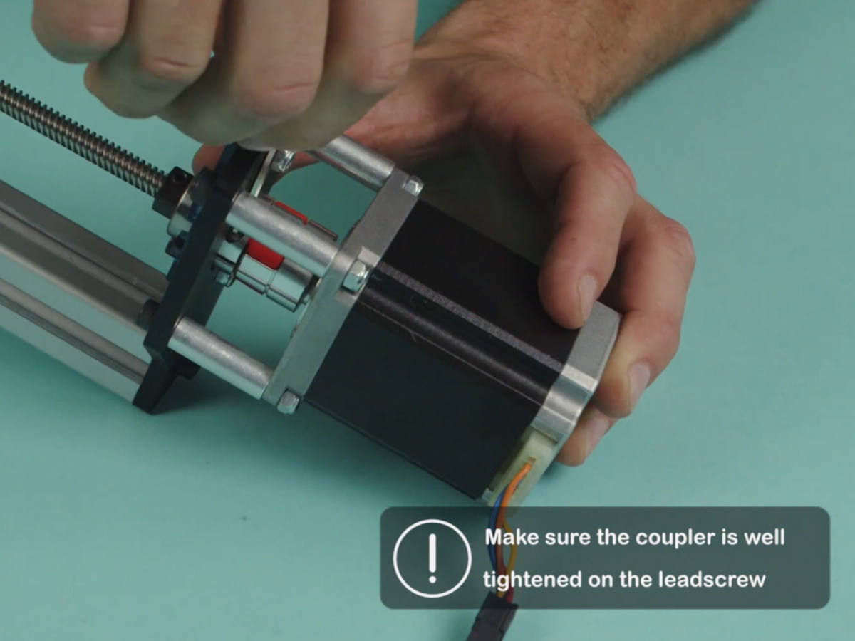
- Insert the leadscrew through the stop ring - until it reaches the motor's coupler.
- Insert the anti-backlash nut.
- When the leadscrew is fully inserted in the motor's coupler, tighten.
- Tighten the stop ring.
Animation