2. Table assembly
Step #05 Mounting the limit switches
List of Components
| DIN 912 Screw | M6x12 | 4 | |
| Sliding Nut | M6 | 4 |
Tools needed

|
Allen Key 5mm |
Instructions
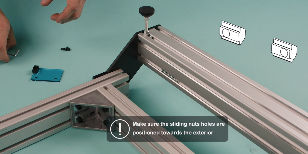
- Insert the two sliding nuts in the profile as shown. The holes must be positioned towards the exterior.
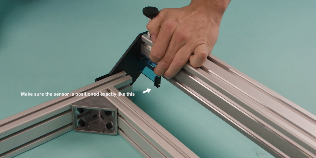
- Place the limit switch with its holes aligned on the sliding nuts.
- Add the two M6 screws.
- Repeat this process for the other side.